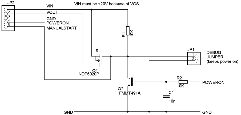
Soft Power On/Off
There is a tendency to be more “aware” of the power consumption of electronic devices and it is common to have them physically switch off power-hungry sections when not in use - more-so in battery powered projects.
The following is a nice simple design that permits just this, whether to save on power usage of specific elements of a design in quiet times, or to turn the whole device off, all under software control.
The circuit is a simple “Hi-side switch” (HSS) based around a P-Type MOSFET which routes power from VIN to VOUT when required. P-Type MOSFETs tend to be a bit more expensive and not generally available in complimentary pairs like traditional transistors. Use of the MOSFET below is a good choice as it is readily available, has characteristics that fit this circuit very well and it is cheap at around $1 or so. HSS circuits using N-Type devices do exist but require a lot of “support” circuitry because of the nature of N-Type MOSFETs. The costs Vs simplicity balance out in favour of the P-Type device I find.
- VIN is the DC power source that is switched to VOUT by the MOSFET Q1. GND is common 0V across the device.
- Taking MANUALSTART to 0V, Q1 will switch on and VOUT will become active. This is useful for if this circuit is to be used to control the whole device. In such cases, the controller must apply a HI to POWERON as soon as it starts so that the power on button may be released. This turns on Q2 which in turn applies 0V to the source of Q1 to maintain power. Applying a LO to the POWERON pin, Q2 turns off and the gate of Q1 is pulled HI through R1, turning Q1 off and so removing power from the VOUT pin.
- The debug jumper holds the gate of Q1 low at all times and so will prevent power being turned off, this is useful in development.
I have used this circuit in several battery-powered projects to provide soft-power-off either on a touch-screen button or on a timer. The push button to power up must be held in to allow the controller to boot. Sometimes this can take a second or so and I like to provide feed-back when the device is awake and under program control. Most often this takes the form of clearing the display to green before building the screen properly, thus the instruction for startup is simply “hold the start button in until the display flashes green”. I have also used it for controlling power hungry modules e.g. radio Transceivers when not required. The circuit is small and compact enough that it easily lends itself to retro-fitting existing projects with a suitable inch-square PCB. If current consumption/switching speed is not an issue, you can probably get away with no heat-sink on Q1 (I've never needed one yet).
Q1 can be any P-Type power MOSFET with a suitably low RDS-on and VGSth below VIN Q2 can be any small NPN signal transistor - time to use all those BC107s ;o)
The usual MOSFET precautions re switching speeds apply. C1 can generally be omitted if Q2 is driven by a good low-impedance signal. It should only be used in noisy environments where problems can be demonstrated as it will slow the switching applied to Q1.

