Gauss Meter
I found this article: http://www.thebackshed.com/windmill/articles/GaussMeter.asp - seems to be no credit on it though - if you know different please update this article.
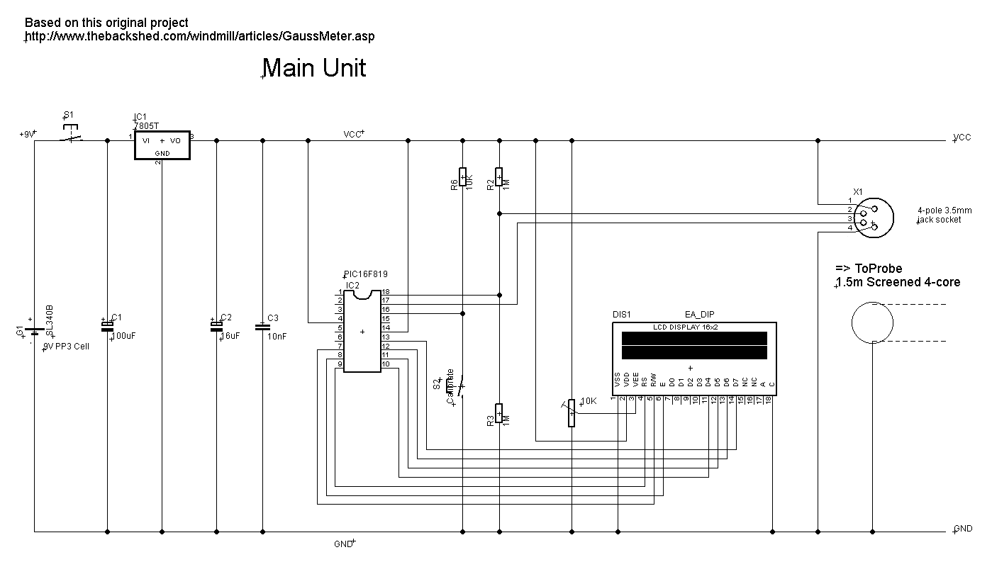
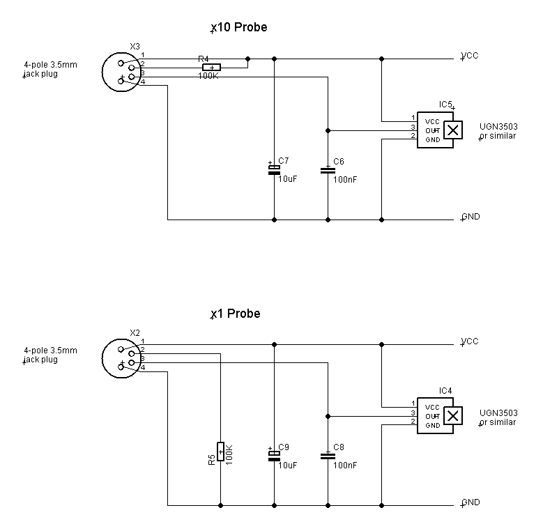
A Gauss Meter is something I have wanted for some time but I needed more than this circuit offered. The Field sensor is quite nice and gives a reasonably calibrated, linear output over it's magnetic range, so I decided to augment the original circuit to include a PIC and LCD to give a more precise reading and to provide two different probes (auto detected) that provide x1 and x10 ranges. NOTE: this isn't a professional unit so only use its readings as a reasonable approximation.
The UGN3503 sensor is a 5V device so best to run on a PIC at 5V which precludes a micromite (this would have made the software easier and a 28pin beastie is £5 so there is no reason not to use one if you can).
The sensor is centre-zero at ~2.5V, with South poles reading below this and North above, at 1.3mV per Gauss (or 13mV per mT) so 2.5V / 1.3mV gives a theoretical maximum of around 1900Gs although the device doesn't swing to the supply rails and you'll get a maximum of N/S 1300ish. Tests show ~1320+Gs - nice. There are two inter-changeable probes using a 4-pole 3.5mm jack plug/socket (get gold plated if you can), the x1 with the sensor mounted right at the extremity of the probe and x10 with a plastic packing piece which reduces the magnetic field by 10 (as measured on the sensor). You'll have to get this just right - with a single iron magnet (i.e. low Gauss so as not to swamp the sensor), measure it ON the sensor then move it away until the reading is ten times lower - measure that distance and that is the size for your packing piece. TIP: measure with the sensor you intend to use in each probe, i.e. use the sensor for the x10 probe for the packing piece measurement. This minimizes any tolerance error. The probes are auto-configuring - AN1 measures the voltage divider R2/R3 and a pull-up or pull-down resistor in each probe provides the intel for the processor to decide how to interpret the measurement. For the measurement, I used a plastic ruler with blue-tack to hold the setup. It makes it easy to slowly slide the magnet up and down but will hold it in place when you let go.
It is important to remember what Gauss is a measurement of. You can't simply stick a magnet on the sensor and say it is an x Gauss magnet - even a small weak magnet will swamp the sensor at 0mm and appear to be the same density as a powerful neodymium magnet. You need to measure the magnets a set distance from the sensor and apply a multiplication factor. As an example here, on a breadboard I had a prominent capacitor and a small magnet near the sensor but on top of the capacitor measured at 22.5Gs. A cube NIB in the same position came in at 394.3Gs. Both placed on the sensor gave a FSD reading, see what I mean? Read this article to get a better understanding: https://en.wikipedia.org/wiki/Gauss_(unit). I find it helps to think of the magnet as a fan. The magnetic flux is represented by the airflow. If you sit right on top of it, even a small fan appears to have a good force, but on the other side of the room, the effect is much attenuated - that is a good place to measure its force in more meaningful terms for this illustration.
The sensor should have a fairly precise packing piece inserted between it and the test subject which will reduce the sensitivity. Magnetic flux follows a rule similar to the inverse-proportion laws of light, radio energy etc. It is rough but generally acceptable and is given as 1/r3 where r is the radius (read; distance) from the subject. So basically, magnetic flux density drops off rapidly as the cube-root of the distance between the flux source (a complex subject in its own right) and the point of measurement (the sensor). Using this equation we can develop a multiplication factor so even very large magnets can be measured reliably. This will reduce the resolution still further (down to about 20Gs per bit) but increase the range substantially.
Measuring the output voltage with the PIC's ADC and converting to Gauss is fairly straight forward. The code uses fixed point maths with everything multiplied by 1E+6 to preserve precision and simply formatted right at the output. The ADC is only 10 bits wide so the 5V/1024 means I can only measure to a resolution of 4.88mV. This is way above the 1.3mV of the sensor but is probably good enough for hobby use. A 12bit ADC would get me to 1.22mV which is nice but small (read: inexpensive) PICs don't have 12 bit ADCs :o(
The code compiles to ~1.5K so you do need a PIC with that at least 2K of flash (so the 16F818 won't do).
The unit boots to a greeting for two seconds to allow everything to stabilise then auto-calibrates itself to find the centre-point of the sensor. During this time, keep the probe well away from magnetic fields. This is used as a reference point for all further measurements. If you think it isn't calibrated right (hint: check the number top right - mine always seems to be around 524 - ideal would be 512), check for possible magnetic contaminants near the probe (tools, CRTs etc.) and press SW2 to jump to the calibrate routine. You can omit SW2 and R6 and just power cycle the whole unit but I wanted to avoid the delay at start up - it's pennies.
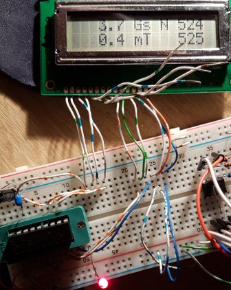
Here it is lashed up on the breadboard (ignore the stuff to the right) - you can see the reference and present reading on the right hand side of the display. It illustrates that with a 10bit ADC (actually 9bit because readings can be either side of the centre for FSD) gives us a resolution of 3.7Gs. The display also shows milliTesla which is Gs/10 but I round up or down to make it more meaningful so 7.5Gs is 0.8mT)
Code:
' Gauss meter, based on this article:
' http://www.thebackshed.com/windmill/articles/GaussMeter.asp
'
' Controller code uses 16F819 (wanted to use up stock of 16F628 but it doesn't have a proper ADC)
'
' Single push button applies power to the device. Keep the wand away from magnetic sources during boot.
' It measures the output of the UGN3503 which is centered around 2.5V and this measurement is our reference
' (It should be about 1/2 FSD of the ADC). Volts on the ADC is (5/1024) = 4.882mV per bit. This is quite course
' and gives a resolution worse than 3Gs. An ADC with 12 bit resolution would get us to 1.22mV per bit which is
' close to the UGN3503 of 1.3mV/Gs.
'
' So need a small PIC with 12bit ADC for a better Gauss meter. If you use a different device, change the #CHIP line
' to suit and set #define ADCBits= to the number of bit on its ADC, Everything else will drop into place.
'
' It's auto-calibrating - The midway point on the sensor may not be exact but we measure it as a reference.
' On the UGN3503, 0Gs is ~2.5v, below that is South, above North. We measure with the ADC during boot and subtract
' the reference if the reading is above 1/2FSD or subtract it from the reference if it's below to give an absolute
' value for North/South (and we set a flag). Then convert to true volts - all voltages are  multiplied by 1e6 to
' maintain accuracy in a LONG. Divide this by 1300 (0.0013*1e6) to get Gauss reading. Actually we divide by 130 to
' get a single decimal. Perfect (but unlikely) range is thus (5/0.0013)/2 = N/S 1923.0Gs or 192mT with a 0.66mm
' packing piece between the direct-contact surfaces of the sensor and the magnet.
'
'*************************************************************
; ----- Configuration
  #chip 16F819, 4

  #config osc=int
  #config wdt=off

  ' #include
  ' no solution specifc includes, default includes are always included                                  ; no solution specifc includes, default includes are always included


; ----- Define Hardware settings
  ' this is required to tell the microprocessor the port is an output


    ' Have to use fixed point maths so multiply everything
    ' by 1e6 to maintain accuracy


    '#DEFINE mVPG=130           ' mV per Gauss = 0.0013 * 1e6  /10 gives xxxx.x

    ' Use LCD in 4 pin mode and define LCD pins
    #DEFINE LCD_IO     4
    #DEFINE LCD_SPEED  MEDIUM  'FAST, MEDIUM or SLOW.
    #DEFINE LCD_RW     PORTB.1
    #DEFINE LCD_Enable PORTB.2
    #DEFINE LCD_RS     PORTB.3
    #DEFINE LCD_DB4    PORTB.4
    #DEFINE LCD_DB5    PORTB.5
    #DEFINE LCD_DB6    PORTB.6
    #DEFINE LCD_DB7    PORTB.7

    ' Here are various LCD commands which can be used.
    ' These are the LCD commands for the HD44780 controller
    #DEFINE clrHome = 1     ;clear the display, home the cursor
    #DEFINE home    = 2     ;home the cursor only
    #DEFINE RtoL    = 4     ;print characters right to left
    #DEFINE insR    = 5     ;insert characters to right
    #DEFINE LtoR    = 6     ;print characters left to right
    #DEFINE insL    = 7     ;insert characters to left
    #DEFINE lcdOff  = 8     ;LCD screen off
    #DEFINE lcdOn   = 12    ;LCD screen on, no cursor
    #DEFINE curOff  = 12    ;an alias for the above
    #DEFINE block   = 13    ;LCD screen on, block cursor
    #DEFINE under   = 14    ;LCD screen on, underline cursor
    #DEFINE undblk  = 15    ;LCD screen on, blinking and underline cursor
    #DEFINE CLeft   = 16    ;cursor left
    #DEFINE CRight  = 20    ;cursor right
    #DEFINE panR    = 24    ;pan viewing window right
    #DEFINE panL    = 28    ;pan viewing window left
    #DEFINE bus4    = 32    ;4-bit data bus mode
    #DEFINE bus8    = 48    ;8-bit data bus mode
    #DEFINE mode1   = 32    ;one-line mode (alias)
    #DEFINE mode2   = 40    ;two-line mode
    #DEFINE line1   = 128   ;go to start of line 1
    #DEFINE line2   = 192   ;go to start of line 2

Start:

    DIM xx      AS LONG
    dim yy      AS LONG
    dim zz      AS LONG
    DIM ref     AS LONG
    DIM nn      AS BYTE
    DIM mm      AS INTEGER
    DIM LN      AS STRING * 5
    DIM tLN     AS STRING * 5
    DIM NS      AS BIT
    DIM decimal AS BIT
    DIM fg      AS BIT
    DIM xc      AS BYTE

    DIR PortA.0 IN
    DIR PortA.1 IN
    DIR PortA.7 IN

    LCDCMD(mode2)
    LCDCMD(lcdOn)
    LCDCMD(clrHome)
    PRINT " LogiTEL (C)2017"' need a space after a clrhome... dunno why
    LCDCMD(line2)
    PRINT "Magnetometer 2.0"
    PAUSE 2000

Calibrate:
    ' Calibrate. Run thru on power up and jump here on pushbutton
    LCDCMD(clrHome)
    PRINT " Calibrating..."

    repeat 10
      ref=READAD10(AN0) ' use the ADC a few times just to settle it
    end repeat

    xx=0

    FOR nn=1 TO 100     ' average of 100 readings
        LCDCMD(line2)
        PRINT STR(nn)
        print "%"
        PAUSE 10
        xx=xx+READAD10(AN0)
    NEXT

    ref=xx/100

    LCDCMD(clrHome)

Main:

    repeat 25           ' wait for 25x10mS rather than 250mS in one lump to make the calibrate
                        ' button a bit more responsive - same ting. Doesn't need debonce coz
                        ' calibration takes about 1sec
      if PORTA.7=0 then goto Calibrate' calibrate pushbutton - pull-up through 10K
      pause 10
    end repeat


    LCDCMD(line1)        ' coz of clrhome

    zz=READAD10(AN1)
    select case zz      ' work out which probe we are using
      case <250         ' ~0V is the x1 probe
        decimal=1
      case >750         ' ~5V is the x10 probe
        decimal=0
      case else
        print "Check Probe"
        LCDCMD(line2)
        print zz
        print "  "
        goto Main
    end select

    zz=0
    REPEAT 1024         ' average loads of readings
        zz=zz+READAD10(AN0)
    END REPEAT
    xx=zz/1024
    zz=xx

    IF xx<ref THEN      ' normalise the bits to an absolute reading of north or south
        xx=ref-xx:NS=0  ' south
    ELSE
        xx=xx-ref:NS=1
    END IF

    xx=(xx*4882)/130

    yy=xx

    FmtLN(yy,5)

    PRINT " Gs "

    IF NS=0 THEN
      PRINT "S "
    ELSE
      PRINT "N "
    end if

    print ref
    print "  "

    '1mT=10Gs
    LCDCMD(line2)

    FmtLN((yy+5)/10,5)  ' round for mT

    PRINT " mT   "

    print zz

    print "  "

    goto Main


    Sub FmtLN(vv as long, fl as byte)
      fg=0
      LN=STR(vv)
      DO WHILE LEN(LN)<fl ' pad with leading zeroes for fixed width so we get xxx0.0 format
          tLN="0"+LN
          LN=tLN
      LOOP
      for nn=1 to fl
        if decimal=1 then
          if nn=fl then
            print "."
          end if
        end if

        xc=asc(LN,nn)
        if xc<>48 then fg=1
        if nn=fl then fg=1
        if decimal=1 then
          if nn=(fl-1) then fg=1
        end if

        if fg=1 then
          print chr(xc)
        else
          print " "
        end if

      next
    end sub
Two files attached top right are the PCB foils for the probes


